
The Viking 140 Turbo
We have multiple engine options available and will help you find what engine will work best for your mission and application.
Viking 140T Information

We see a bright future for this model
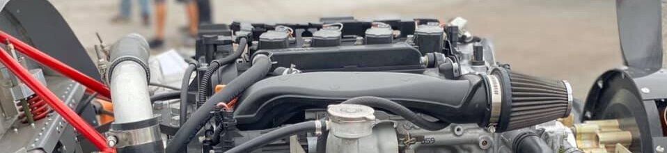
The 140 HP Turbo engine has a great power to weight ratio. With over 625 lb. of thrust, the engine can be boosted for STOL flights and competitions. As a cross country powerplant, it is light, fuel efficient and will maintain power past 15,000 feet.


Type: 1.2L, Direct Injected, Inline 3-cylinder Turbo with balance shaft
Horsepower: 150 @ 5800 RPM
Weight: 220 lbs.
Gearbox Ratio: 2.33/1
Compression Ratio: 10.0/1
Bore and Stroke: 2.953 x 3.563 / 75 mm x 90.5 mm
Block Material: High Pressure Die Cast Aluminum
Takeoff RPM: Engine 5400 / Prop 2400
Cruise RPM: Engine 4900 / Prop 2100
Static RPM – STOL: Engine 5400 / Prop 2400
Static RPM – Cross Country: Engine 4800 / Prop 2100
Idle RPM: 1400-1600 RPM
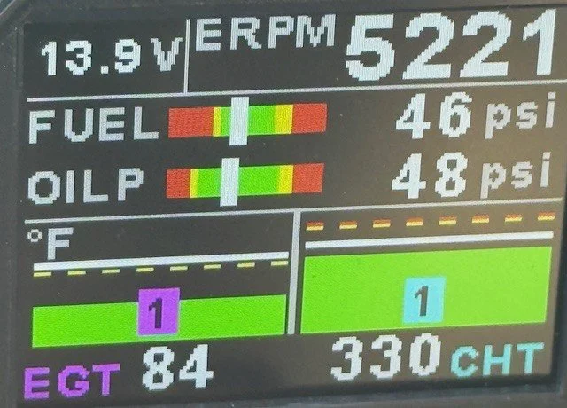
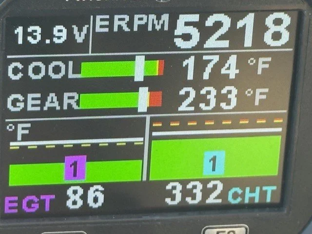
Coolant Temperatures: 200 – 220 F
Oil Temperature: Not Measured
Oil Pressure: 20 – 125 Psi
Fuel Pressure: 43 Psi from Header tank to the engine.
Fuel: 89+ Octane or higher grade - 100LL (MUST use Decalin and is not the preferred fuel.
Length: 23 in.
Height: 25 in.
Width: 22 in.
Gearbox Oil: 75W-90 Mobile 1 Synthetic Gear Oil (8 ounces), 75W-140 Mobile 1. 10ounces of gear oil should be used with the 48 state gearbox or the X gearbox (after 2022).
Gearbox Temperature: Should not exceed 240 Fahrenheit.
Engine Oil: 5W-30 and MUST BE DEXOS type.
Coolant: Evans NPG Plus
Coolant System Pressure: 0 Psi
Maintenance:
Engine Oil Change: Every 50 hours (4 quarts) MUST BE DEXOS type.
Gearbox Oil Change: Every hour for the first 10 hours, then every 25 hours

METRIC MEASUREMENTS
ENGINE DETAILS
Engine Block:
The cylinder block is constructed of aluminum alloy by high-pressure die casting. It has 3 cast-in-place iron cylinder liners arranged in-line. The block has 4 crankshaft bearings with the thrust bearing located on the second bearing from the rear of the engine. The cylinder block incorporates a bedplate design that forms an upper and lower crankcase. This design promotes cylinder block rigidity and reduced noise and vibration.
Crankshaft:
The crankshaft is forged micro alloy steel. It is supported in 4 main journals on main bearings which have oil clearance for lubrication. The thrust bearing is located in the 3rd position which controls proper crankshaft axial end play. The crankshaft is also comprised of 4 counterweights that have been scalloped for mass reduction and topped for precise engine balance. A harmonic balancer is used to control torsional vibration.
Piston and Connecting Rods:
The pistons use 2 compression rings and 1 oil control ring assembly. The piston is a low friction, lightweight design with a recessed top and barrel shaped skirt. The piston pins are chromium steel and are a full-floating design. The connecting rods are powdered metal. The connecting rods are fractured at the connecting rod journal and then machined for the proper clearance. All applications use a piston with a graphite coated skirt. The piston and pin are to be serviced as an assembly.
Lower Crankcase Extension:
In the lower crankcase extension, the oil pump is installed.
The oil pump is directly driven by the crankshaft. The oil pump draws engine oil from the oil pan and feeds it under pressure to the various parts of the engine. An oil strainer is mounted before the inlet of the oil pump to remove impurities which could clog or damage the oil pump or other engine components. When the crankshaft rotates, the oil pump driven gear rotates. This causes the space between the rotor to constantly open and narrow, pulling oil in from the oil pan when the space opens and pumping the oil out to the engine as it narrows.
Balance Shaft
The balance shaft reduces noises and vibrations. It sits in the engine block and is driven via balance shaft gears by the crankshaft.
Cylinder Head
This cylinder head is of the double overhead camshaft (DOHC) type. It is made of cast aluminum alloy for better strength, hardness, and is light weight. The combustion chamber of the cylinder head is designed to increasing squish and enhance swirl efficiency to maximize the gasoline combustion efficiency. The exhaust manifold is integrated into the cylinder head.
Valves
There are 2 intake and 2 exhaust valves per cylinder. Positive valve stem seals are used on all valves. Valve Lash Adjusters use a roller finger follower acted on by a hydraulic lash adjuster. The roller finger follower reduces friction and noise.
Camshaft Cover
The camshaft cover has crankcase ventilation baffling incorporated. The camshaft cover has mounting locations for the ignition system.
Camshaft
Two camshafts are used, one for all intake valves, the other for all exhaust valves. The camshafts are hollow to save weight and are assembled with steel lobes.
Intake Manifold
The intake manifold is the air flow passage to the cylinder combustion chamber through the throttle body and has an effect on engine torque, power, noise, emission, fuel economy and performance. It is made of composite plastic.
Turbocharger
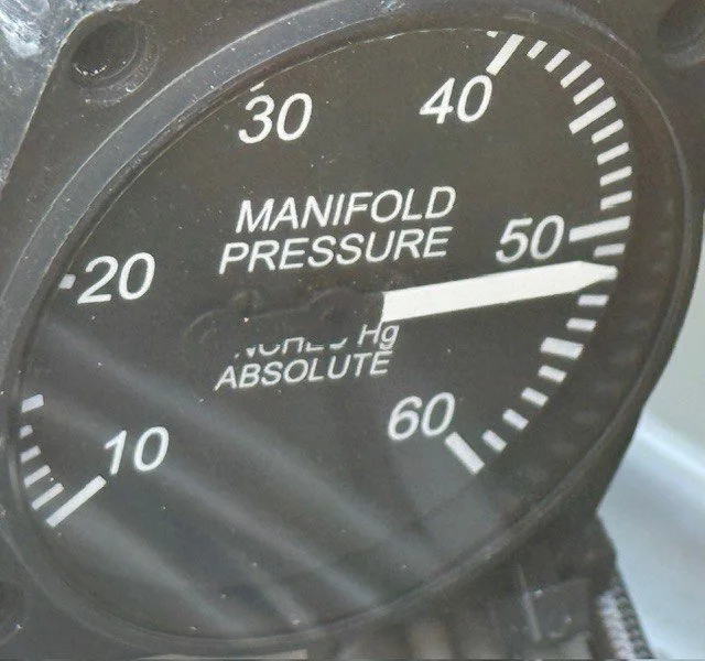
The turbocharger supplies compressed air from the turbine/impeller to the engine to increase power. With the variable turbine geometry turbocharger, the boost pressure is optimized in all engine conditions.
Fuel Injection System
The engine is equipped with a central direct injection system. The fuel system consists of 3 separate direct injection fuel injectors, one high pressure fuel rail, and a high pressure fuel feed pipe that connects the high pressure fuel pump to the fuel rail. The injectors are each seated into their individual bores in the cylinder head with a combustion seal. The high-pressure fuel pump mounts to the front of the cylinder head and is driven by the intake camshaft. Motion is transmitted to the pump from a tri-lobe on the rear of the camshaft through a hydraulic roller lifter. Due to the location of the central direct injection system injector location this provides an increase in fuel economy and performance.