
FUEL
***PLEASE NOTE: THE REMOVAL OF ANY GEARBOX REQUIRES A NEW CENTERING BUSHING, EVERY TIME***
3 Gallon Header Tank


Header Tank Brace for the 3 Gallon Header Tanks - Some are sent in one/others in 2 pieces and can be rivetted together.
When mounting 3 Gallon Header Tank, to ensure angle/height:
Step one would be attaching the tank in the front/to the bottom of the rear baggage bulkhead with the angled bracket.
Step two is to level the tank with the top of the fuselage so that it will be level during flight.
Fuel Filters: Do not install fuel filters in the engine compartment
Please note some of the new 750's will require the mounting straps to be laid out differently due to a design change with the Zenith fuselage. This will likely change the design of the quick drain adapter as well. The back baggage area used to be lower, allowing the header tank to be lower, now it has to be mounted higher and a little further aft. The flanges on the cross brace should face aft, not forward.


If you ever have to change a pump/maintenance. Boil used gaskets for one hour in water to shrink them back down. Then lube with O-ring lube. Or, alternatively, you can get a new O-ring.

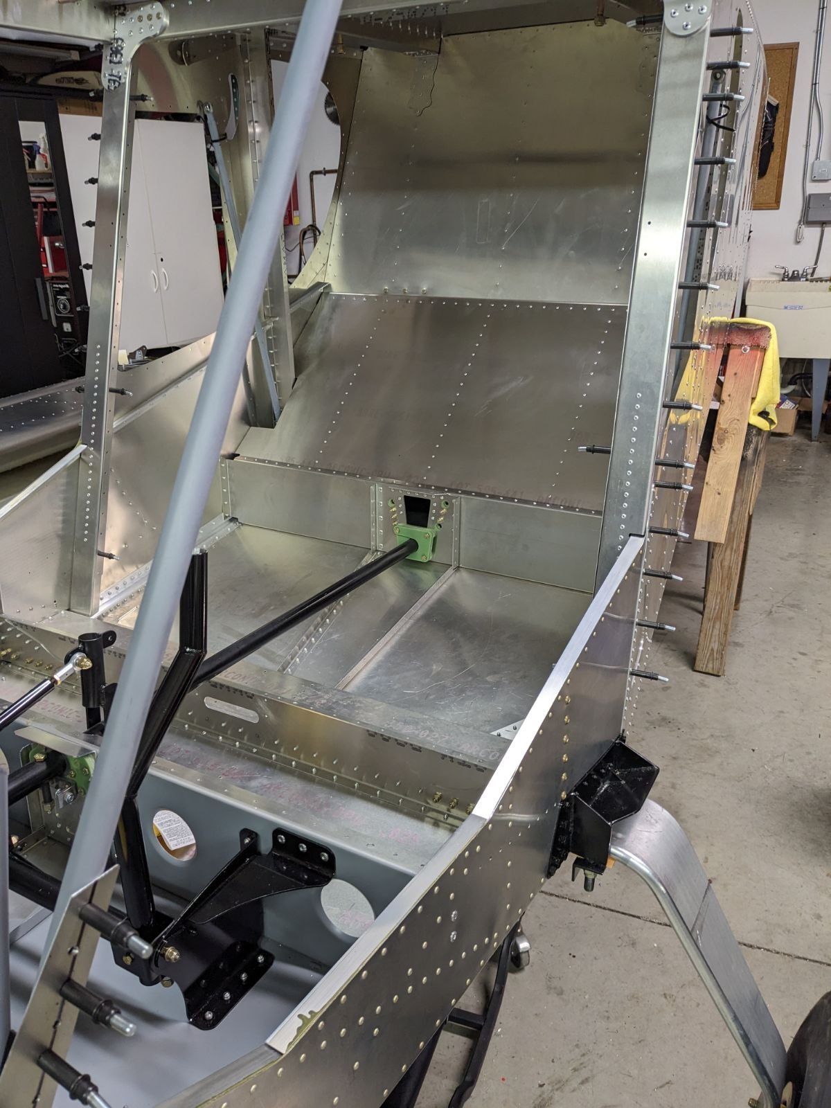
ACCESS PANEL
Highly recommend adding in an access panel in the aft area of the fuselage for easier maintenance to your fuel system and other components. See an example in the pictures below.

Aft Mounting in any Aircraft if Moving CG Aft

RANS S21 Fuel System Install
Rans S-21 fuel system
Plumbing is the same as for Zenith aircraft. Just use the installation videos.
One top port of the header tank is used to bleed any air back to the main tank. Attach this to the main tank at the top of the left or right fuel sight glass, using an appropriate T arrangement. This arrangement has been tested for over 500 hours in an S-20 with the Viking 130.


Please view the many installation videos in order to end up with a fuel system as shown in this picture. The low winged system is similar but uses a small header sump instead of the 2.5 gal unit.

Mini Header Tank Installation and Information
For the Low Winged crowd
After testing several methods to improve the flow of fuel to the centrally located fuel mini header tank, one method has been found to be superior to others and is the only one recommended by Viking.
However, right now it works down to near no unusable fuel if the 2 tanks flow at the same time.
The fix was to install forward facing vents on the tanks. The original vents do not provide any pressure and might even cause a suction at times.

For Zenith low wing applications, note the following:
The Zodiac plans call for the fuel hose coming from the wing tank to pass through the first rib several inches above the bottom skin. This works for a system that has a fuel pump but not for gravity feed. Although the wing tilts at about 5° slope, you don’t have access to the last few gallons of fuel especially in the turn.
The plans also call for the hole in the fuselage side to almost correspond horizontally with the finger screen in the fuel tank. In order for effective gravity feed, you have to cut a new hole for the line. This is also where it is positioned with a customer new hole.

This picture shows the new routing through the first rib downstream from the fuel tank. This position provides a slight down slope and restores gravity feed.

In order to effectively cut a hole in the next rib just prior to the side of the aircraft, you either have to take the wing off or cut an access hole in the bottom skin and then plate back over it.
Mini Header Tank Installation (High Wing)
Install a feed line from each tank to the bottom two ports of the header tank.
Route at least one vent line back to one wing tank (ideally both) from top of header tank.
If additional ports are needed, as for instance, for a drain install a brass street tee.
Be sure to install pre-filters prior to the header tank.
Mini Header Tank Installation (Low Wing)
Install a feed line from each tank to the top two ports of the header tank.
If additional ports are needed, for instance, for a drain install a brass street tee.
Be sure to install pre-filters prior to the header tank.
WARNING: Never obstruct either of the two feed lines from the wing tanks with anything such as; a valve, transfer pump or anything else. The system works without dedicated additional vents because the two wing tanks are always connected through the header tank.
Also, be sure to run fuel lines as low in the aircraft as possible to provide continuous gravity feed to the header tank
Be sure to install the forward facing additions to the bottom vent tubes as shown in the picture above and forward facing siphon brake brass elbows in the fuel caps.
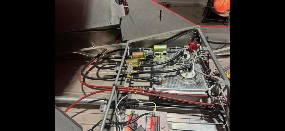
Keep in mind older style pumps face up and newer systems face down
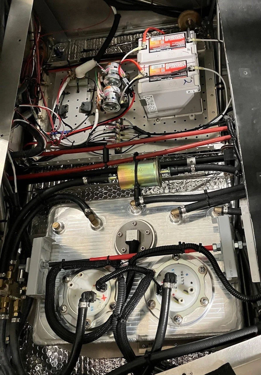
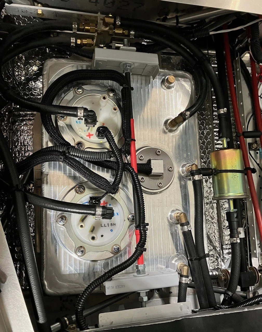
New Style 2021 and After Mini Header Tank (Pumps Installed from the Top Down)

Mini header tank for single tank aircraft
A SOLID FUEL SYSTEM IS IMPORTANT FOR ANY AIRCRAFT ENGINE. THESE ARE THE SYSTEMS USED BY THE THREE MOST POPULAR LIGHT AIRCRAFT ENGINES IN USE.
ROTAX
Dual external fuel pumps
External single fuel regulator
Fuel return commonly back to primary fuel tanks
6 port duplex fuel selector valve
VIKING
Dual in-tank pumps
In-tank dual fuel regulators
Header tank based system
No fuel valve needed
UL
Dual external fuel pumps
External single fuel regulator
Fuel return commonly back to primary fuel tanks
6 port duplex fuel selector valve
EXTERNAL FUEL PUMPS
UL and Rotax use external fuel pumps for their injected engines. They are a copy of what was used in cars prior to 1998.
When 2 pumps are used together, for takeoff and landing, the amperage draw can be 10-14. This is a lot since these engines are not equipped with good alternator systems. Even with a single pump running, the draw is scary high if either the generator or external voltage regulator were to fail. The dual fuel injectors and sparkplugs cannot work without electricity.
External pumps produce close to 2 x the required fuel pressure for the injectors. The excess pressure is regulated back down, using an engine mounted fuel regulator. Excess fuel is returned to the fuel tank.
All this additional fuel, when returned, brings heated fuel to the tank. The total fuel circulating between the main fuel tank and the engine, then returned, is about 30-35 GPH.
Due to the excessive fuel circulating, the amount of fuel gravity fed to the firewall mounted pumps is also 30-35 GPH. Hence the large hoses specified.
Rotax and UL each use a single fuel regulator at the end of the fuel rail, mounted to the hot, air cooled cylinders. The Rotax brand is likely to be Bosch but the UL is a no-name copy. Each is filled with rubber parts and will fail, sooner or later.
This is now an antiquated way to feed fuel to a fuel injected engine.
EXTERNAL FUEL REGULATOR
What is the big deal about a fuel regulator? Well, what is the big deal about a wing attachment bolt?
The external fuel regulator is the single point of failure in a UL or Rotax injection system.
An external regulator requires external fuel return hoses.
The regulators used are automotive quality and have a definite life span.
The engine ECU (control computer) knows nothing about fuel pressure. If the pressure is wrong, the engine will not operate correctly, no matter how many sparkplugs it has.
A single fuel pressure regulator is not consistent with any other dual capability. The engine cannot run without it. ASTM was never informed of this.
INTERNAL FUEL PUMPS AND FUEL REGULATORS
The Viking fuel system does not use a 35 gph gravity drain system, a single fuel regulator or a complex 6 port fuel selector valve.
The Viking system is based on dual, in- tank pumps, each equipped with its own fuel regulator.
Each pump draw less than 1.6A and has no external fuel return hoses.
Only the amount of fuel used by the engine is gravity fed from the main fuel tanks to the header tank
A fuel level gauge measures the exact fuel level of the header tank, providing accurate fuel gauging.
ISSUES RELATED TO SYSTEMS DRAWING/RETURNING FUEL TO/FROM A MAIN FUEL TANK
A fuel injected engine MUST have a solid fuel pressure at all times, or the engine will stop
Having reliable gravity feed, all the way from the wing tanks to the firewall mounted pumps, of 30-35 gallons / hour is much harder than the 2-12 GPH that the engine is actually using. When this system was used by cars, the pump was mounted right below the fuel tank.
There is an illusion that these systems work because fuel usually come out of the pump when turned on. What is not so obvious is how small the margin is for the system to stop working.
It is likely that even though the pump was never designed to pull fuel on the suction side, that in the airplane application it actually does this to keep up with demand. Since there is suction, any air leak prior to the pump has the potential for pump cavitation. An O-ring leak in a fuel drain, gascolator or selector valve would not be good.
Since the fuel is at low pressure (suction) as it enters the hot engine compartment, any exposed metal fuel pump body or fuel system component could cause the fuel to boil and cavitate the pump, dropping the pressure from 43.5 psi to less than 10 psi. Once the pressure has been dropped, the pump will not be able to re-gain pressure due to the 43 psi fuel regulator at the other end of the engine fuel rail. (Here is where a small bleed bypass around the pressure regulator would be handy but this is not implemented by either Rotax or UL. The bleed would allow some fuel to flow, re-priming the pump with fresh fuel and again be able to make pressure)
A larger amount of unusable fuel. Because more fuel is being returned to the tank, than is used by the engine, fuel is on the move in the tank and not always available at the pickup location. To guard against this, more fuel must be kept in the tank, shortening the available range. Also, as the fuel level decrease in the tank, the warm return fuel becomes more and more pronounced and pump cavitation is even more likely.
Serious concern of un-porting the fuel pickup location. As mentioned above, one second without fuel pressure is one second the engine will not operate. Carbureted engines have a fuel bowl from which the engine can draw fuel. Not so with an injected engine. There has to be fuel available to the pump at all times. With low fuel, and in an extended descent, this is usually not the case. Some installations add more complexity to the system by the installations of door-post mounted “sumps” in order to have some protection from this. However, keep in mind that these fuel pockets only last for a few seconds when the system wants to pump 35 GPH in a circle. The pump will draw the fuel from the pocket in no time flat, bringing back the un-porting issue.
THE FUEL SELECTOR VALVE
The UL and Rotax systems usually use a duplex / 6 port fuel selector valve. These are complex, costly and have 6 fuel line connections right inside the cabin. Another style is from a pickup truck with dual fuel tanks. These are of terrible quality and are electrically operated. Cut one open and inspect the construction if considering using one. Again, there is no backup so be sure it works.
Viking does not use a fuel selector valve. Fuel simply drains from the two wing tanks into a single header tank. From there, no selection is required. The popular C-150 also has no fuel selector.
WHY IS THE VIKING SYSTEM BETTER AND HOW DOES IT WORK?
The Viking system consists of a header tank and two fuel pumps. That’s it. Fuel fills the header tank by gravity. If the engine uses 6 GPH, the system only has to flow 3 gallons from each wing tank. (only about 1 qt every 5 minutes)
The pumps are inside the tank and submerged in fuel, just like every modern fuel injected car. The fuel regulators are right on the pump bodies, pre-filer screens are part of the system, etc. A precise fuel sender unit and gauge are available, allowing the main tanks to be used to a lower level with complete confidence. The 30 min VFR daytime reserve is in the header.
CAN I USE A VIKING HEADER TANK WITH A UL OR ROTAX ENGINE?
The short answer is – yes you can. Viking has such a system and has been successfully tested on a UL engine. The long answer is much more complex and you need to understand it if you are contemplating such a conversion. Here are the details.
First, it is important to understand how the original system works and the reason for why things are the way they are.
Fuel pumps: The fuel pumps are big, heavy and draw a lot of current for a reason. In order to reliably produce 43 psi of pressure, additional capacity is used, and then regulated down. Because the pumps are external to the fuel, they are only cooled by the fuel running through them and by convection. If the pump slowly got hotter and hotter during operation, a vapor situation would surely occur.
In order to use fuel for pump cooling, excess fuel needs to flow through the pump. Most systems run 3-5 times more fuel through the pump than what is used by the engine. The main reason the fuel is returned back to the fuel tank is to cool it. The fuel also cools the fuel rail and purges air from the rail when first primed for starting.
If we eliminate the large pumps, we also eliminate some of the heat put into the fuel. Some fuel must still be returned to the header tank since these fuel rails are not designed to purge air without a return at the last injector. A small amount of return also helps cooling the fuel injectors.
Below video shows our older style cylindrical header tank setup