
VALVE LASH AND ADJUSTMENT
***PLEASE NOTE: THE REMOVAL OF ANY GEARBOX REQUIRES A NEW CENTERING BUSHING, EVERY TIME***
Valve Lash measurement and adjustment (Viking 130)
Tools:
#5 hex key
10mm socket
Torque wrench
Flathead screwdriver
Feeler gauge set
Paper towels
Red RTB sealant
Blue threadlocker
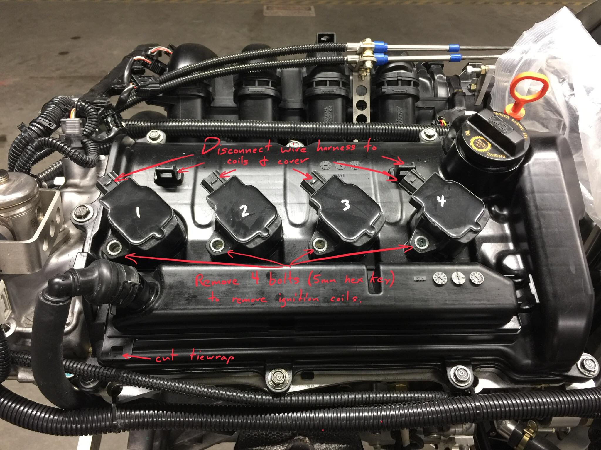
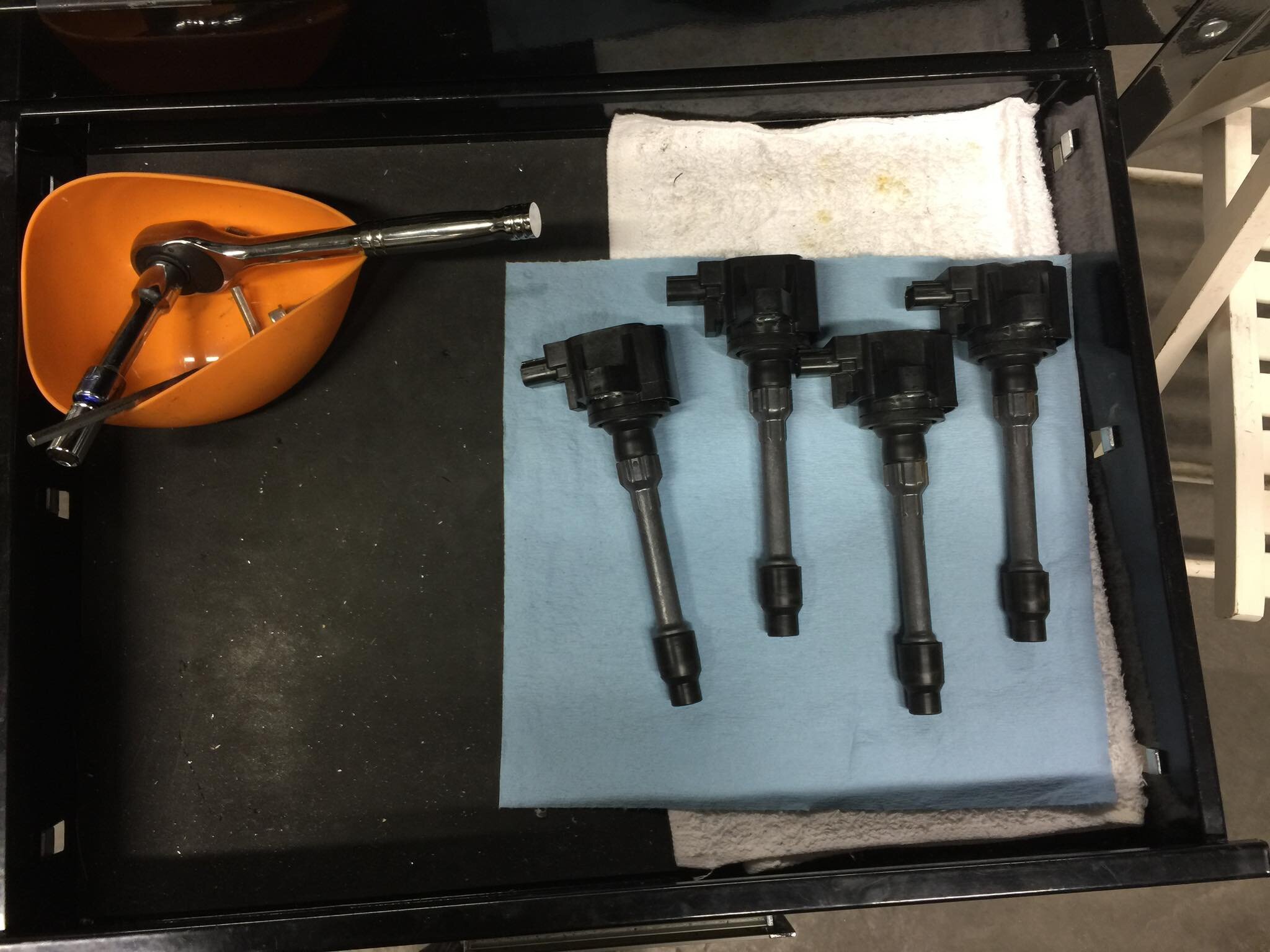
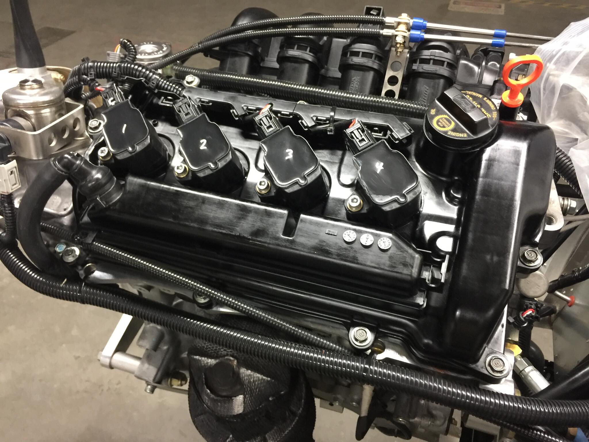
Remove the ignition coils by disconnecting the wiring harness and removing each bolt (#5 hex key).
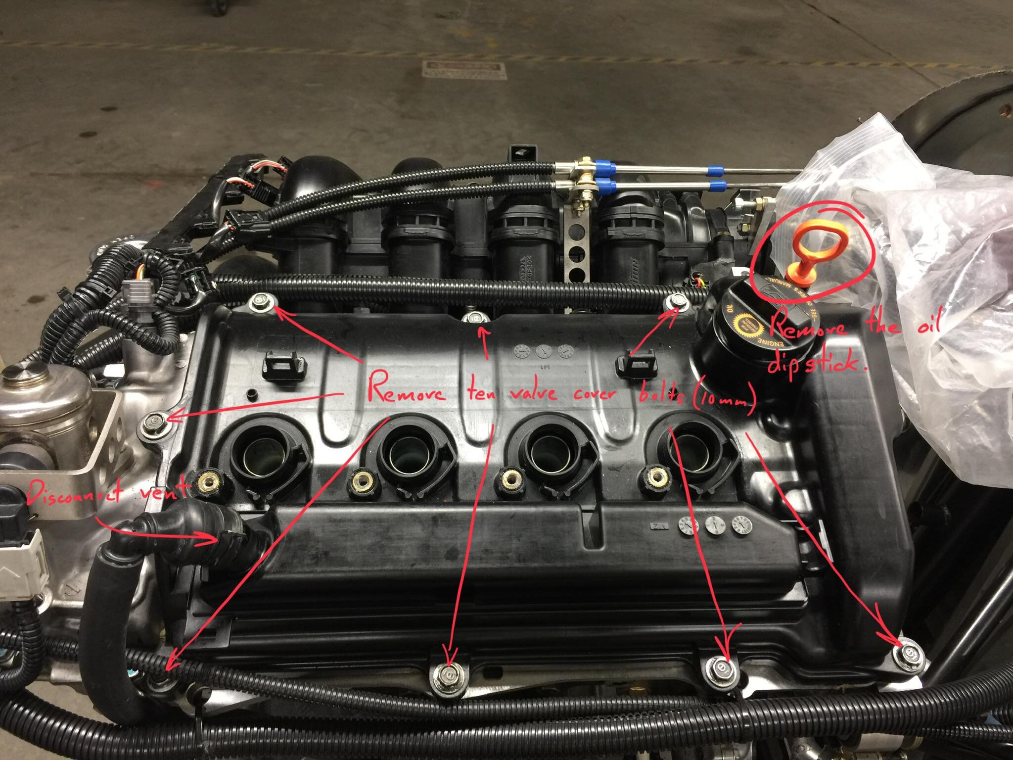
Remove the oil dipstick.
Disconnect the breather vent.
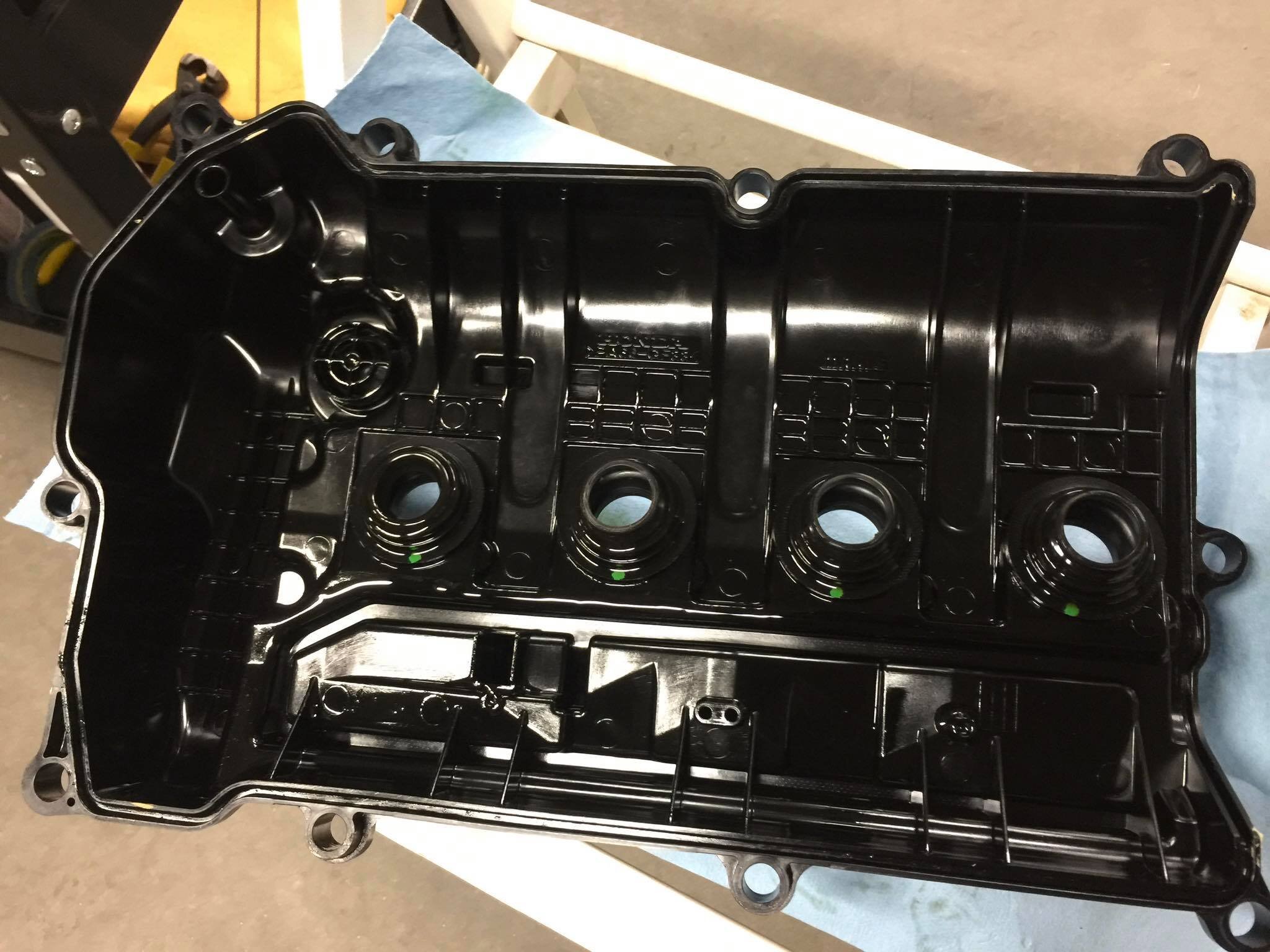
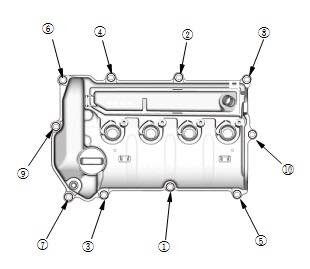
Remove the cylinder head cover bolts (10mm) and remove the cylinder head cover.
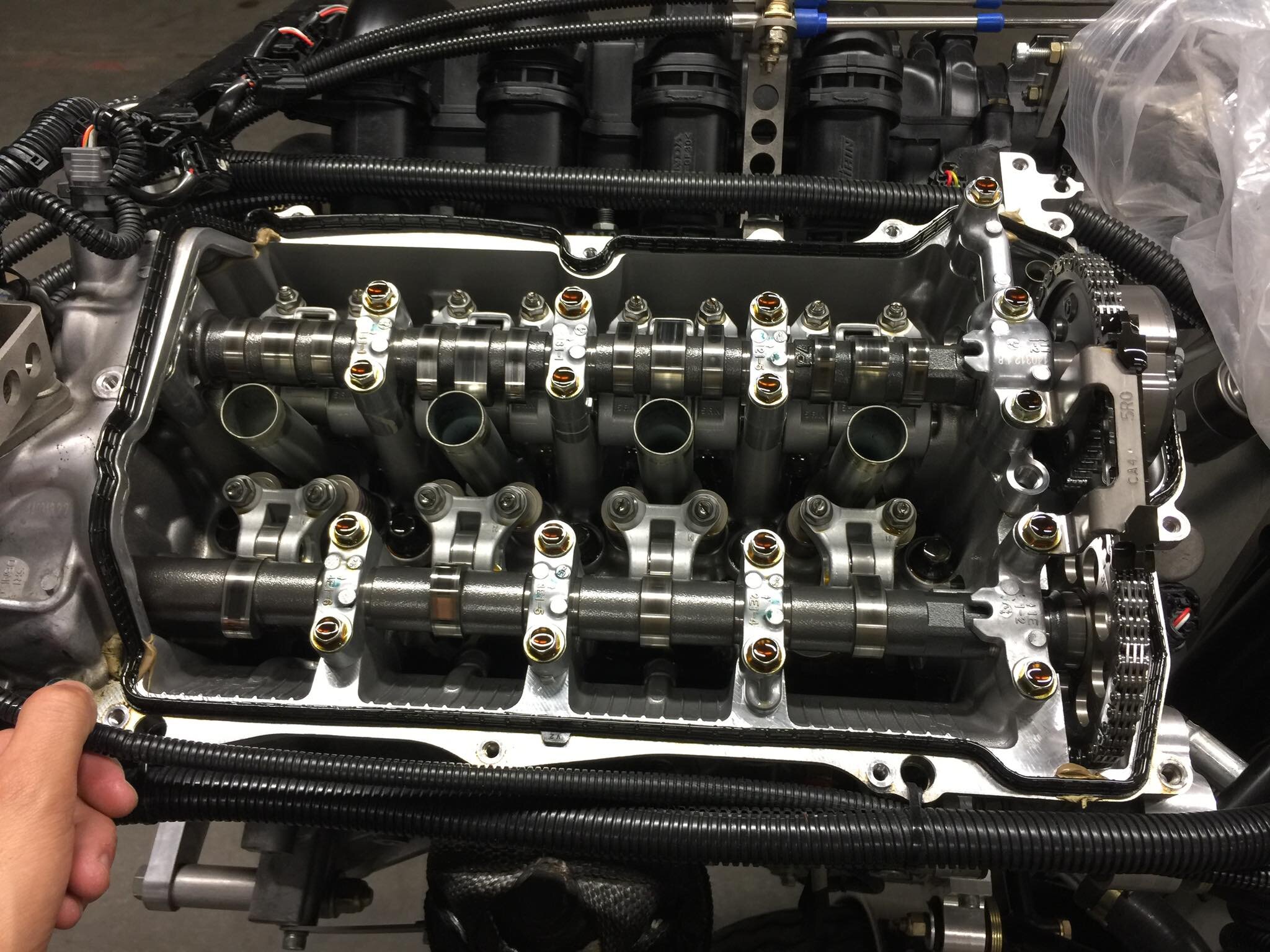
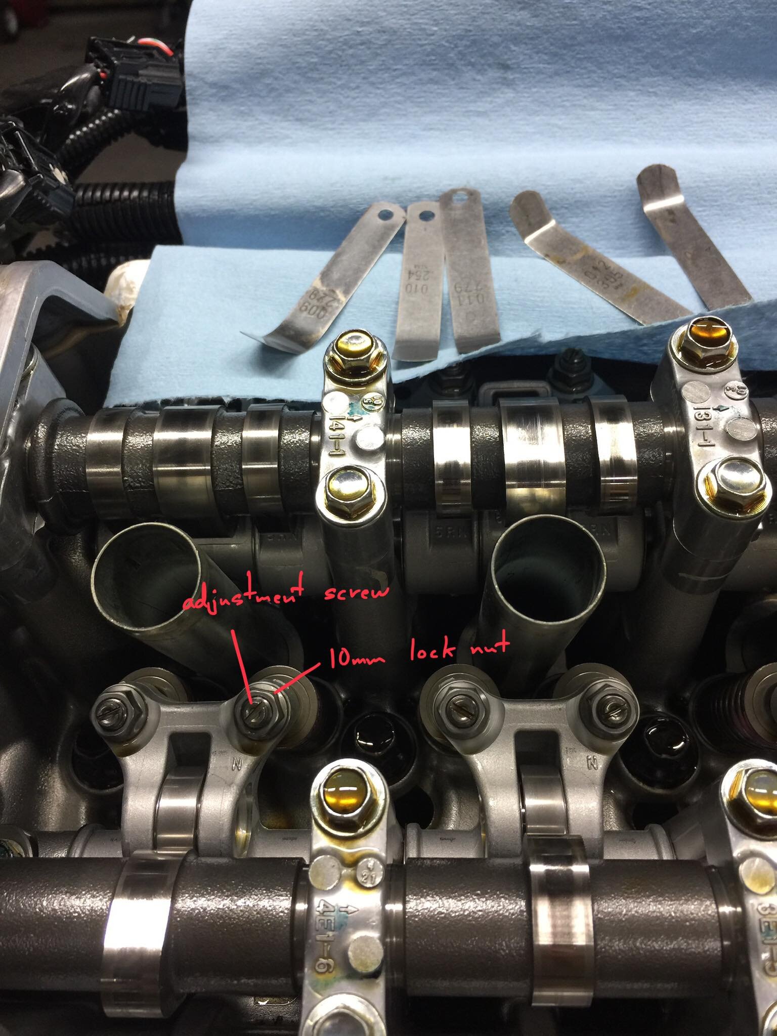
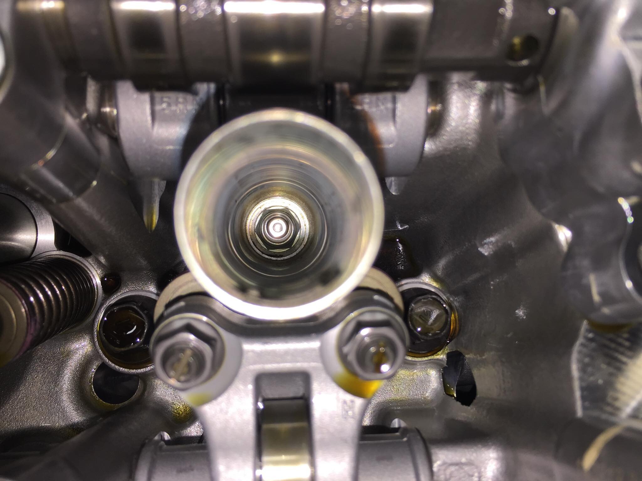
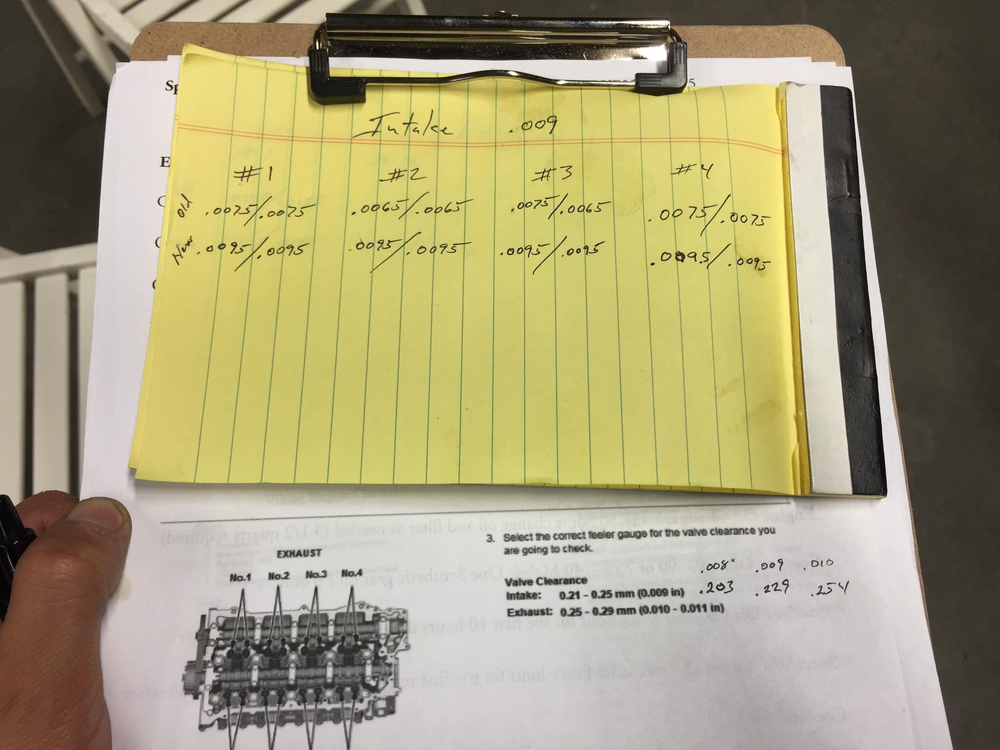
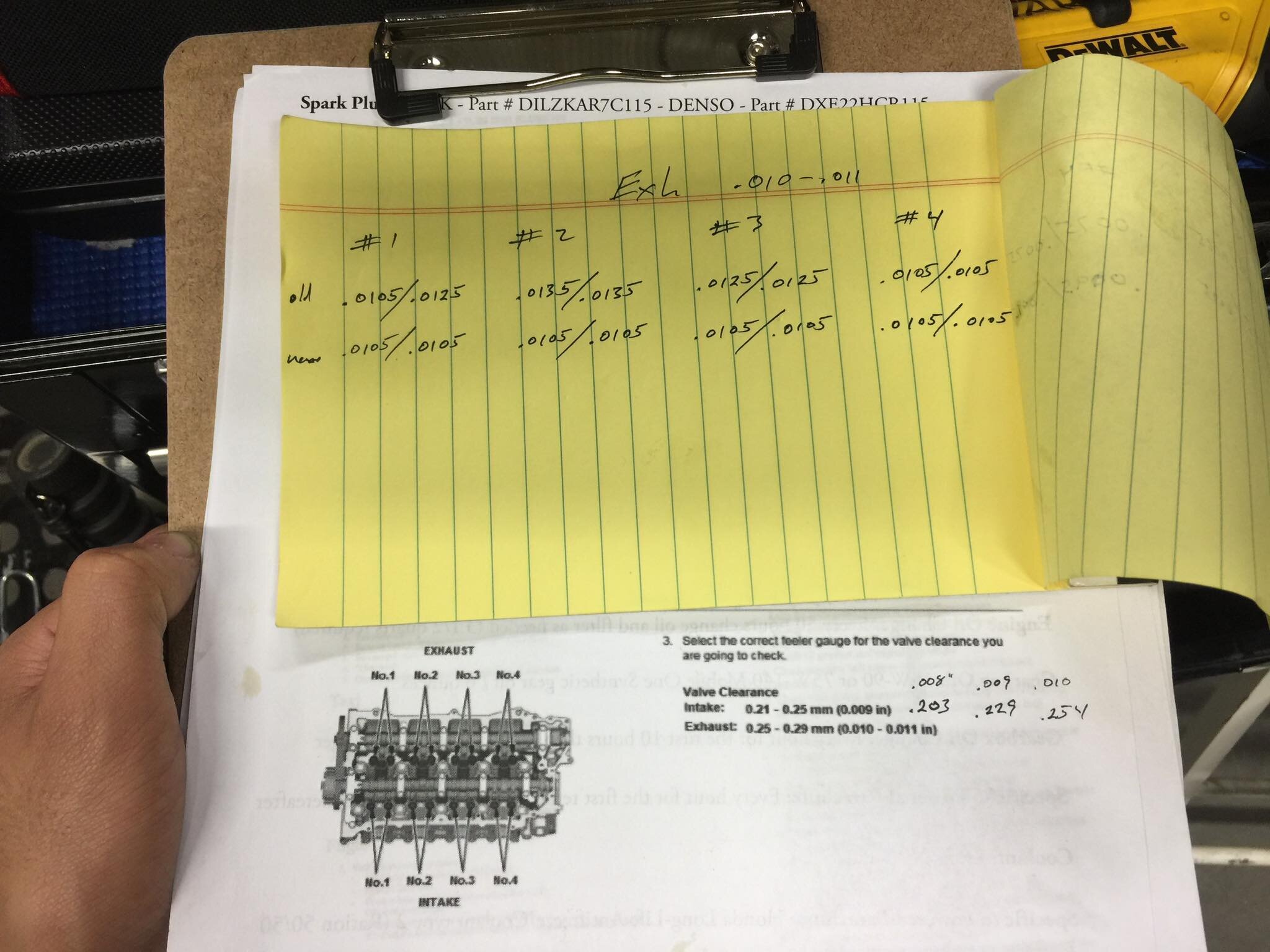
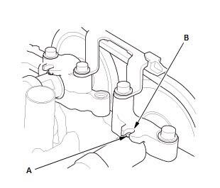
To measure valve lash, first rotate the engine so that cam lobe is not pushing against the respective rocker assembly. Valve lash is measured with a feeler gauge between the tappet adjusting screw and the end of the valve stem. A feeler gauge measurement is either a go or no-go.
Intake 0.21-0.25 mm (0.009 in)
Exhaust 0.25-0.29 mm (0.010-0.011 in)
To adjust valve lash, loosen the locknut (10mm), and turn the tappet adjusting screw until the drag on the feeler gauge is correct. Then while holding the tappet adjusting screw with the screw driver, tighten the locknut, then recheck the clearance. Repeat the adjustment, if necessary.
Reassemble and reseal.
Tappet locknut (10mm), torque 10 lbf·ft
Ignition coil bolts (#5 hex key), torque 9 lbf·ft
Cylinder head cover bolts (10mm), torque 5 lbf·ft
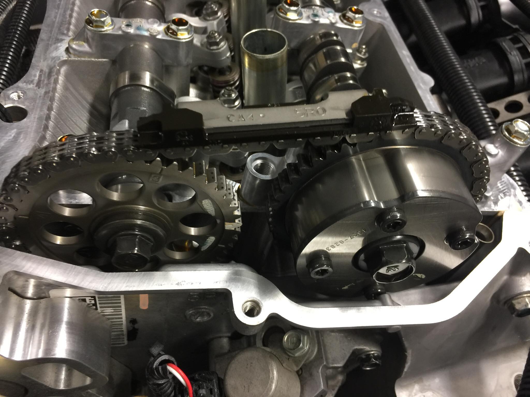
Note: cylinder fire order is 1, 3, 4, 2 and where cylinder 1 is closest to the cam chain (aft).

VIKING 140T
No valve lash check needed - it has hydraulic lifters
Spark plug torque - 12ft lbs / 150 inch lbs
Ignition coil bolts - 150 inch lbs