Zenith Super Duty/750 STOL Tail End Plates


Zenith Super Duty/750 STOL Tail End Plates
Tail End Plates for the Zenith Super Duty or Zenith 750 STOL. They do not work without modifications on a 701.
PLEASE NOTE THESE ARE NOW NOT PREPUNCHED DUE TO UNIVERSAL FIT
They effectively increase the power of the horizontal stabilizer by preventing tip losses. Because the horizontal stabilizer on the Zenith is such a high lift device (downward) the gain is quite large.
The reason we use them is in extreme slow flight with reduced prop wash over the tail the increased tail force helps to keep the nose up for a shorter landings and takeoffs.
Darrin Towers:
“I mounted the end fences with a bunch of Clecos and did some taxi testing. Wheely down the runway test..So with the end fences on I can get the nosewheel off the ground and keep it only about 6” off the ground at around 25 mph indicated. Repeated and got about the same. Then removed them and tried it again, it takes a lot more power to get the nose up then to maintain it I had to be going at least 32 mph indicated.”

Once I came up with a plan to orient the blank end plate to the horizontal stabilizer and elevator, the hole layout began to fall into place. Since the plane is polished aluminum, decided to polish the Plates. CYCLO polisher and NUVITE.
I had not built the plane so, this was the most metal work that I have done to the aircraft, so might have over thought it a little bit, but this is more or less how I approached it.
Needed to set a base reference point. So......
Had picked up a 43” flat screen for the hangar a while back and had saved the container it came in. The box provided large pieces of firm Coated cardboard to make templates of the hor. stab and chart elevator travel up & down . Traced the outline of the hor. stab with elevator in full UP andDOWN position. Then while still held in place , MARKED the locations of the existing rivets and the elv. hinge / pin by pressing cardboard ,( coated side towards the plane ) , against them. Rivets make nice Dimples, hinge pin leaves a small hole at it’s location. Cut it out and , good to go.
Trace the outline of an end plate on another piece of cardboard and start to move stuff around .
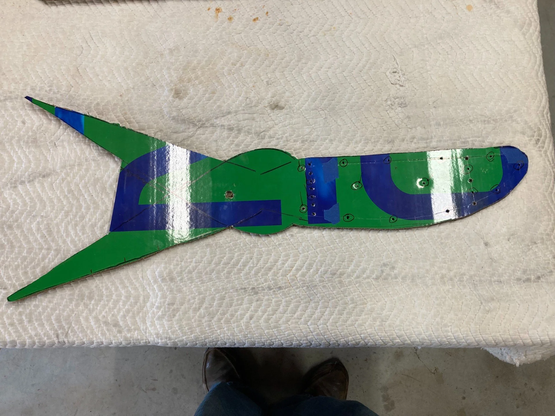


Once the hor. stab and elv. travel piece is cut out , ( with hinge and existing rivet locations established ), figure out the relation ship you want between the end pate, leading edge of the hor. stab. , how much of the plate goes above / below the hor. stab.and the elevator travel / arc.
Started out thinking about the relationship between the hor stab and the end plate . Work from the front back .... But ended up doing just the opposite .
Instead of making it equal space top and bottom with an arbitrary distance from the front of the end plate to the leading edge of the stabilizer, I figured that since I would Never fly with a Full Nose down elevator, BUT do use a lot of NOSE UP for a power on high AOA short field landing : laid it out to keep the elevator “inside” the end plate with the elv. full up. So , at least for me, it was the relationship between the elevator and the end plate that largely determined where the plate would attach to the horizontal stabilizer.
The idea was the keep the elv. “ behind “ the end plate, top to bottom AND to keep the elevator travel arc inside the end of the plate. These two factors helped to determine where to transfer the rivet and hinge locations to the end plate template. ( Now I can better appreciate why you are sending the end plates out with NO pre-drilled holes. ).
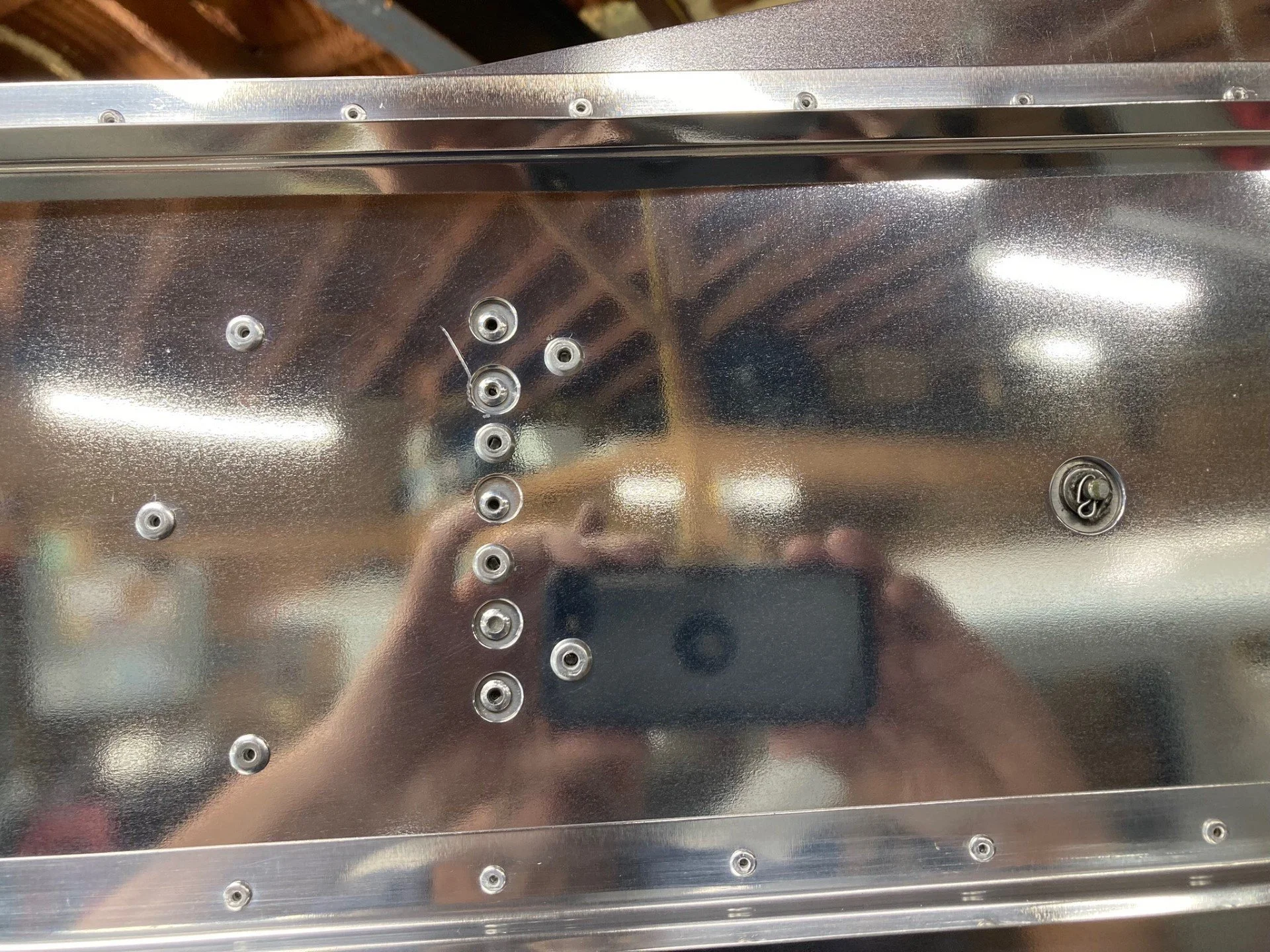
Square up the two pieces : Since the Zenith hor. stab is an inverted airfoil , everything has to referenced from the Top . Once locations are marked , drilled over sized holes to allow the existing rivets and hinge to come through the end plate.

I had longer lengths of “Zenith Angle” so decided to use them , vs the shorter ones that came with the Plates. And to use two , one high , one low , rather than one low . Also, I mounted them up away from the bottom of plate and in from the ends. If someone were to walk into the tail they would make contact with the heavier , flatter, end plate vs a protruding piece of angle aluminum.


The last 5 rivets on stiffeners are set from the inside to provide more clearance for elv. travel.
I hit the forward and aft spars with a larger rivet than used to connect with the horizontal end plate.
The top of the end plate is parallel to the top of the hor. stab.
By using two longer stiffeners , there does not appear to be excessive plate travel , in / out , towards the elevator. So for the present there are no spacers being used to hold the end plates out away from the elevator.
And..... even though the left and right side horizontal stabilizer and elevator should be exact mirror images....... double checked that the template created for one side was truly a 100% reflection of the other side before marking / drilling existing rivet and elv. hinge holes. To hit all the marks, hinge , front rivets , rear rivets AND be parallel with the top of the hor. stab. , everything has to match. It took a little longer , but laying out Each end panel and drilling them separately , allowed for minor differences to be seamlessly compensated for.